Astigmatic polarized beamlets
Standard stigmatic beamlets are limited to symmetric systems. For the modeling of arbitrary optical systems, including off-axis components, tilted lenses, or complex media like atmospheric turbulence, the package provides the AstigmaticGaussianBeamlet. This type implements the astigmatic Gaussian beamlet ray tracing formalism initially proposed by Greynolds (1986) [15, 16].
However, this idea has been referred to in multiple ways over the last few decades, including but not limited to: Gaussian Beamlet Tracing (GBT), Fat Ray Tracing (FRT), Parabasal Ray Tracing (PRT), Complex Ray Tracing (CRT), Gauss Beamlet Propagation (GBP) and Beam Synthesis Propagation (BSP).
Formalism
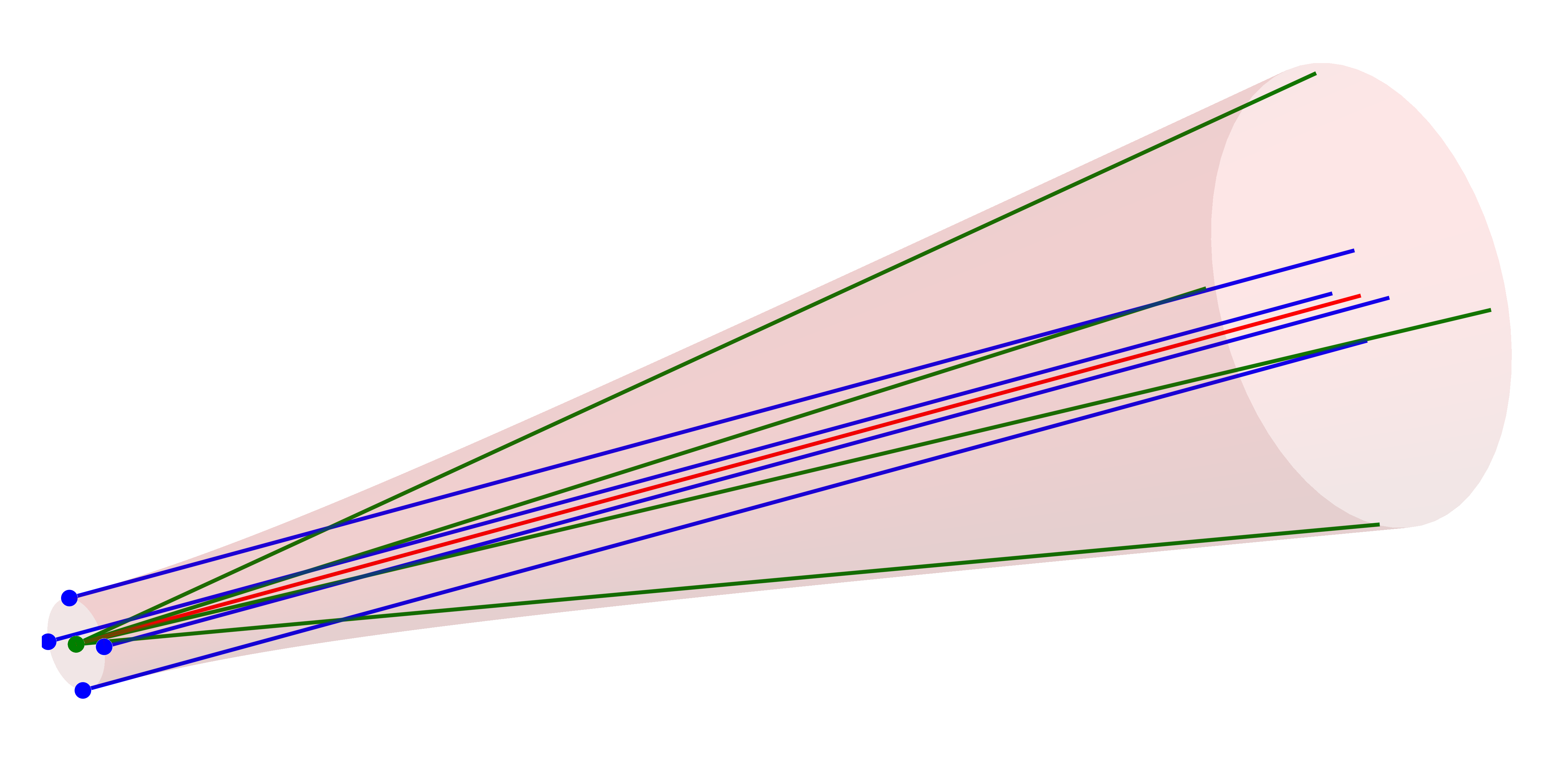
Similar to the Gauss model presented in the Stigmatic beamlets chapter, an astigmatic beamlet can represented by a cluster of 9 rays:
Ray representation
Chief Ray: a
PolarizedRaydefining the central path and polarization state.Waist Rays: four "positional" rays (waist
Divergence Rays: four "directional" rays (divergence
These rays can be thought of tracking the complex curvature matrix
Key assumptions
Paraxiality: the auxiliary rays must remain within the paraxial regime relative to the chief ray.
Parabolic interaction: since only astigmatism can be captured, each surface interaction must be approximately parabolical
Homogeneous polarization: the polarization state of the traced field is assumed to be homogeneous over each beamlet
Matched scale: the beamlet must be smaller than the optical element it interacts with, see also 2.
The initial ordering of the geometric beams/rays is shown in the figure below. The colors represent the chief (red), waist (blue) and divergence (green) beams.
As with the GaussianBeamlet, tracing these rays through a system allows the reconstruction of the waist envelope and electric field. The reduced complex amplitude of the Gaussian beamlet is computed as
where
The linear polarization state is visualized by an oscillating red line and is proportional to the on-axis peak field strength.
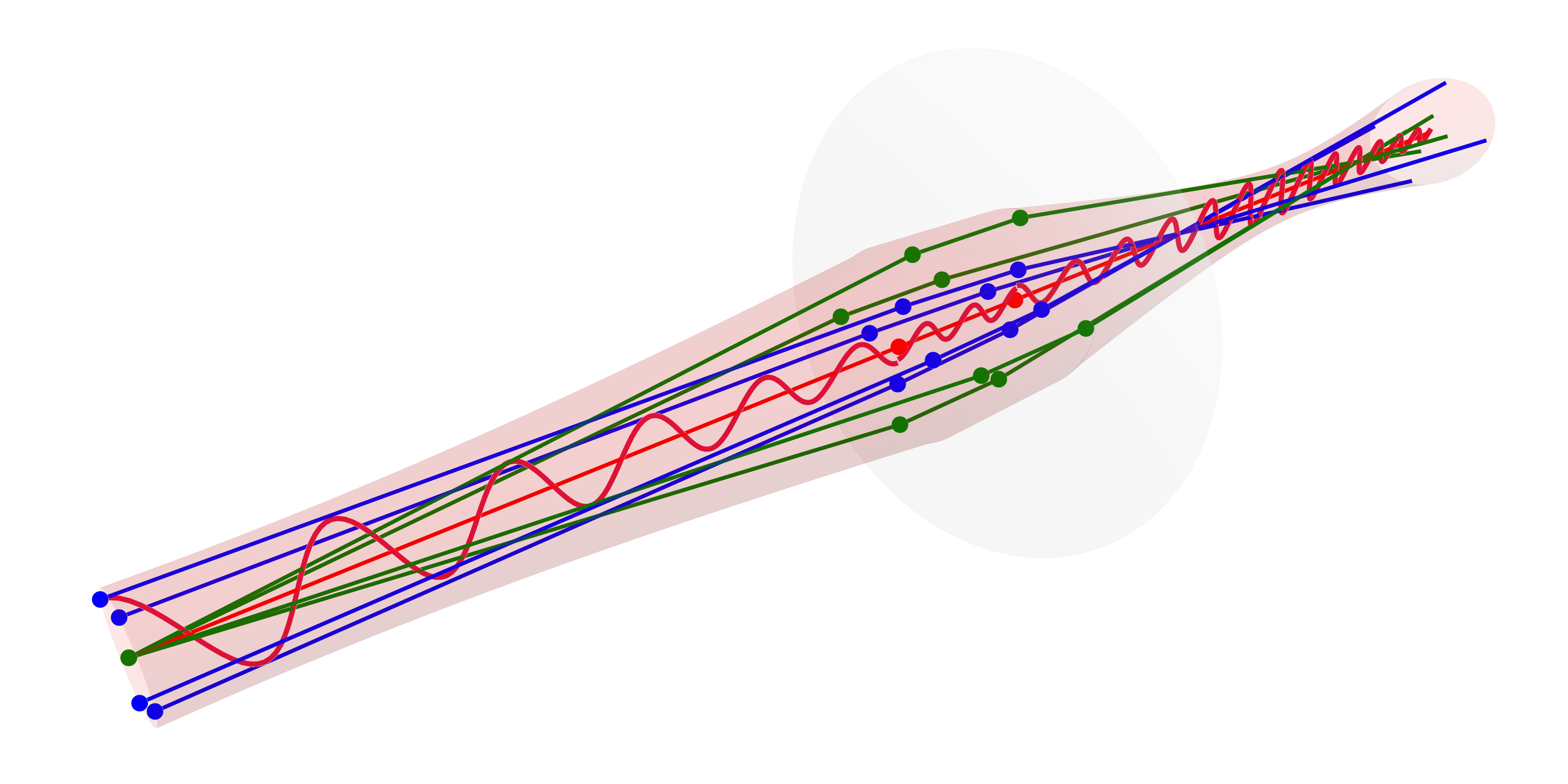
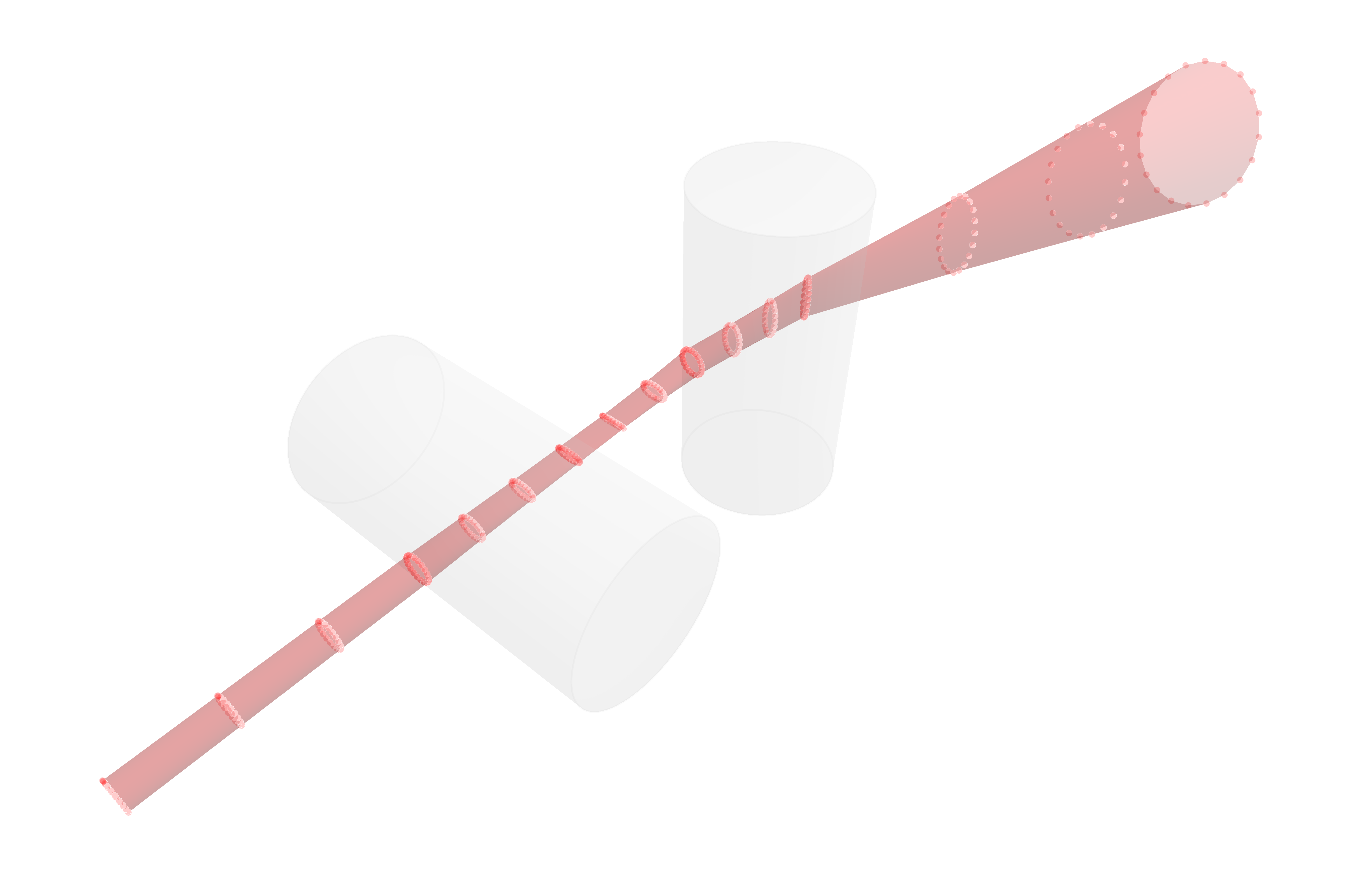
While the above beam closely matches the example Gaussian given in the previous section (Obtaining the beam parameters), the real advantage of this extended method lies in the tracing of non-symmetric systems. For a tilted two cylinder lens system, the following result with strong astigmatic effects is obtained. Multiple waist slices are marked with red dots.
The phase factor due to the optical path length of the central ray (
Optical invariant
In order to ensure the correctness of the traced beamlet, the complex ray vectors must satisfy the vanishing complex optical invariant:
with the analytic bilinear form of the dot product (see below). Tracing stops with a warning if its absolute value exceeds get_invariant_threshold(), by default
The Lagrange invariant get_lagrange_tolerance(), by default 50 %, from its start value, for any
Astigmatic beamlets
You can construct a single astigmatic beamlet with a specified waist and polarization:
BeamletOptics.AstigmaticGaussianBeamlet Method
AstigmaticGaussianBeamlet(position, direction, λ, w0; kwargs...)Constructs an astigmatic Gaussian beamlet at position with the specified beam parameters. In the 4-argument version, the beam has circular symmetry with waist radius w0. In the 5-argument version, independent waists w0_x and w0_y can be specified.
Arguments
Inputs
position: origin of the beamletdirection: direction of the beamletλ: wavelength of the beamlet in [m]. Default value is 1000 nm.w0: beam waist (radius) in [m]. Default value is 1 mm.w0_x,w0_y: independent beam waists in [m].
Keyword Arguments
M2,M2_x,M2_y: beam quality factors. Default is 1P0: beam total power in [W]. Default is 1 mW.E0: electric field vector in [V/m] atposition, it replacesP0. Default isnothing(aligned with support axes, scaled byP0, zero Gouy phase at the waist).support: optional support vector for basis construction, i.e. the X axis of the beamlet. Must be orthogonal todirection, otherwise anArgumentErroris thrown; has any non-zero length and is normalized internally. Default isnothing, i.e. a vector orthogonal todirectionis chosen.z0: beam waist offset in [m]. Default is 0 m
Additional information
Waist offset
As for a GaussianBeamlet, the z0 keyword arg. spawns a beam at the specified position with its waist at an offset z0 in [m] along the chief ray axis.
Optical invariant check
When using the solve_system! function, the beamlet invariant will be checked for each interaction. If the invariant is violated, tracing will be stopped.
Independent waists in the two transverse axes, e.g. of a diode laser, are set with the five-argument constructor:
BeamletOptics.AstigmaticGaussianBeamlet Method
AstigmaticGaussianBeamlet(position, direction, λ, w0_x, w0_y; kwargs...)Constructs an astigmatic Gaussian beamlet with independent waists w0_x and w0_y. This constructor supports modeling astigmatic sources where the waists in X and Y are at different locations along the beam axis.
Arguments
position: Origin of the beamlet.direction: Propagation direction vector.λ: Wavelength.w0_x: Waist radius in the X direction (defined by the support vector).w0_y: Waist radius in the Y direction.
Keyword Arguments
z0_x: Offset of the X waist frompositionalong the propagation axis in [m]. Defaults toz0.z0_y: Offset of the Y waist frompositionalong the propagation axis in [m]. Defaults toz0.z0: Default forz0_xandz0_y. Default is 0 m.M2_x,M2_y: Beam quality factors. Default is 1.P0: Total power in [W].E0: Optional electric field vector in [V/m] atposition, it replacesP0.support: Optional vector orthogonal todirectionto define the X axis. Has any non-zero length and is normalized internally. Asupportthat is not orthogonal to thedirection(the dot product of the unit vectors exceedsget_orthogonality_threshold(), default1e-10) throws anArgumentError. Default isnothing, i.e. a vector orthogonal todirectionis chosen.
Additional information
Optical invariant check
When using the solve_system! function, the beamlet invariant will be checked for each interaction. If the invariant is violated, tracing will be stopped.
The constructor will spawn an AstigmaticGaussianBeamlet which is implemented as follows:
BeamletOptics.AstigmaticGaussianBeamlet Type
AstigmaticGaussianBeamlet{T} <: AbstractBeam{T, PolarizedRay{T}}Complex ray representation of a general astigmatic Gaussian beam as per the formalism described by A. Greynolds (1986) and N. Worku (2017). The beam is described by a chief PolarizedRay and 8 auxiliary Rays that encode the waist radius and divergence in two orthogonal transverse axes. The beam quality M2 is considered via the divergence angle. All equations are based on the following publications:
Alan Greynolds, "Vector formulation of the ray-equivalent method for general Gaussian beam propagation." Curr. Dev. Opt. Eng. Diffraction Phenom. Vol. 679. SPIE, 1986
and
Norman Worku and Herbert Gross, "Vectorial field propagation through high NA objectives using polarized Gaussian beam decomposition." OTOM XIV. Vol. 10347. SPIE, 2017
Fields
c: chiefBeamofPolarizedRaysparent: reference to the parent beam (ornothing)children: vector of child beams (e.g. after beam-splitting)
Additional information
Waist and field calculation
For a given beamlet the Gaussian beam parameters can be obtained via the gauss_parameters function.
Calculating astigmatic beam parameters
The scalar parameters of a traced beamlet are obtained as for the GaussianBeamlet:
BeamletOptics.gauss_parameters Method
gauss_parameters(agb::AstigmaticGaussianBeamlet, z::Real)Compute the scalar Gaussian beam parameters at distance z. Returns a tuple (w1, w2, R1, R2, ψ, w01, w02) where:
w1,w2: beam radii along the principal axesR1,R2: radii of curvature along the principal axesψ: total Gouy phase shift, collected continuously along the beam: it does not jump behind a focus or at a mirror, and a child beam continues its parentw01,w02: waist radii along the principal axes
BeamletOptics.waist_parameters Method
waist_parameters(agb, z)Compute the position and elliptical waist axes at distance z along the beam. Returns (p0, w1, w2, w01, w02) where w1 and w2 are 3D vectors describing the semi-axes of the beam cross-section ellipse.
BeamletOptics.rayleigh_range Method
rayleigh_range(agb::AstigmaticGaussianBeamlet)Returns the Rayleigh range for the x and y axes of the first beam section of the beamlet as a tuple (z_rx, z_ry), from its waist radii and divergence (M2 included).
BeamletOptics.electric_field Method
electric_field(agb, r, z)Convenience wrapper for parabasal_field.
BeamletOptics.intensity Method
intensity(agb::AstigmaticGaussianBeamlet, r, z)Compute the optical intensity n |E|² / (2 Z₀) [W/m²] of the beamlet at position (r, z), with the refractive index n of the segment at z.
BeamletOptics.optical_power Method
optical_power(agb)Compute the total integrated optical power of the beamlet at its start, from the irradiance n |E|² / (2 Z₀) with the refractive index n of its first segment. For a Gaussian beamlet, this is typically constant through lossless propagation.
To obtain the physical vector electric field [V/m] at the transverse offset r from the chief ray, at the distance z along the beam:
# r is an offset vector orthogonal to the chief ray, not a point in world coordinates,
# here along x for a beamlet along +y
E_vec = BeamletOptics.polarized_field(agb, [0.01, 0, 0], 10.0)# Decompose a sampled field into a new AstigmaticBeamGroup,
# with the sample x = y = 0 at pos
group = WavefrontBeamletDecomposition(x, y, amplitude, phase, pos, dir, λ)
# Trace all beamlets of the group through the system
solve_system!(system, group)The Gouy phase follows the argument of the complex beam area
The amplitude changes with the beam area only within a segment. At a surface it follows from the polarization of the chief ray instead: the Fresnel coefficients relate the fields on both sides, and they include that the cross section of the beam changes with the angle of refraction.
All nine rays start in the plane of the chief ray start, so that none of them starts behind an object the beamlet should hit, e.g. when a waist lies downstream of the start, as for a converging beam. The waist rays are parallel to the axis at the waist radius, so they are the same lines wherever they start. The phase includes the optical path correction in media for coherence. The transverse term is a geometric length like
The Curvature Matrix
The relationship between the auxiliary rays and the complex curvature of the beam is defined by the matrix equation
The diagonal elements
Analytic Bilinear Form
All vector operations in the formulas above (
Physical Beam Cross-Section
While the complex curvature matrix waist_parameters function.
As explicitly modeled for general astigmatic Gaussian beams [22], the matrix describing this intensity ellipse is directly derived from
The spatial spot matrix
This identity implies that the spatial spot covariance matrix
BeamletOptics takes the envelope of the field from
Usually
In BeamletOptics, this calculation is mapped directly to the 3D global coordinate system. Using the two complex 3D ray vectors
Expanding the complex vectors into their real and imaginary parts (
To find the true physical principal axes of the general astigmatic beam, the waist_parameters function computes the eigendecomposition of this symmetric matrix